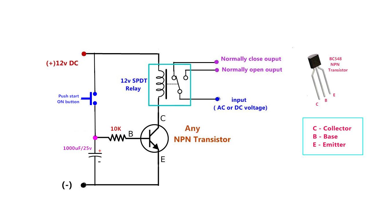

You can also use the diode to act as a snubber to prevent the relay damaging the MOSFETs at switch off. This can be used as a timer circuit and can be applied in the OFF electrical appliances. When the pushbutton is pressed, the relay immediately energizes and sends power to the electric horn. Simulate this circuit – Schematic created using CircuitLabĪt the expense of two more MOSFETs you can solve the problem. Your RC circuit will decay but the MOSFET will stay on. The gate behaves more like a small capacitor so charging it up through the diode will work fine but you won't be able to discharge it. Time delay relay operation Pin 3 provides (after setting) a positive rectangular pulse, whose amplitude is approximately equal to the 12V power supply voltage. It doesn't behave like a regular transistor whose charge will leak away through the base-emitter junction. That was a nice try but the problem is that the MOSFET has an extremely high input impedance and a little bit of capacitance. So i thought that when i press a button, a specific capacitor discgarges and the other 2 will charge, so in order to prevent this I put the diode on the way to the gate (1 diode after each R-C combination). If more than two motors are to be sequenced in this fashion, we would simply scale up this switching arrangement by connecting additional timer relays in parallel with each motor starter so that each motor stops one after the other in the prescribed sequence.I put the diode there because I want to put 3 different combinations of R and C and 3 buttons in order to have 3 different time delays (30, 60, 90 seconds). Once the off-delay coil is de-energized, its contacts will delay for five seconds, then revert to their original state, so motor M2 will continue to run for five seconds after motor M1 has stopped due to an overload. If an overload occurs on motor M2, only that motor will stop, but if motor M1 develops an overload and its OLR contacts open, then the coil will de-energize and its 2-3 holding contact will open, disconnecting the timer coil from the source of supply. It does not need external energy to delay its contacts, that energy is stored in the timer, usually as compressed air or spring tension. It is important to note that even though the timer coil has been disconnected from its source of power, it still performs its timing function. Once pressed, the M1 contactor and the off-delay timer will be de-energized, and their contacts will revert to their original state.įor the motor starter, this will happen instantly, but the timed contacts associated with the timer coil will have a delay of five seconds before they open, during which time motor M2 will continue to run. Once both motor starters are engaged, the motors will continue to run until the stop button is pressed. In this Delay Timer project, all analog parts are being used with the thyristor as a device that switches an AC Relay ON or OFF depending on the timing of the. At power on, C1 charges slowly via R1 and the coil of the relay. The delay is a function of the time constant produced by the combination of R1 and C1. Off delay means the load turns ON immediately, and then load turns off after delay time expires. The contacts will not return to their normal. This circuit is designed to provide delayed relay switching action at power on. Looking at time on delay and time off delay using transistors, capacitors and diodes as well. OFF-delay timers are a type of time delay relay that opens or closes the circuit as soon as power is removed. This is because the normally open contacts associated with the off-delay coil will change their state instantly when the coil is energized. Time Delay Relays, in this video we learn the basics of how time delay relays work. My initial thought was a resistorcapacitor circuit (RC circuit). My Circuit: Coil Voltage Nominal 5VDC Max - 6.5vdc Input voltage 6VDC As I mentioned I am learning. If the start button is pressed both motors M1 and M2 will start instantly. In the below circuit, how can I add a delay when the button is released the relay will stay energized for approx. The above switching arrangement will allow two motors to be controlled from a single pushbutton station.
Power on time delay relay circuit series#
These timed contacts are in series with motor starter M2. In parallel with M1 is a time-delay relay (TR) who’s normally open, timed to open (NOTO) contacts identify it as an off-delay timer. The above circuit shows a standard three-wire circuit for a single-motor starter M1. The magnet pushes a switch to the left, forcing the spring contacts together, and completing the circuit theyre attached to.

Circuits 41 Sequence Control: Off-Delay Definite sequence control off-delay In this relay, when a current flows through the coil, it turns it into an electromagnet.


 0 kommentar(er)
